WildTools 3D Constraints & Rotations |

WildTools 3D Constraints & Rotations |
WildTools 3D introduces a new form of angle constraint, in addition to the two familiar ones.

Choose this for unconstrained angles in the current view plane. When you choose this option, the tool will draw in the current view plane only-and angles and lengths will be in the current view plane. Use the Shift key to constrain the angles.

Choose this for constrained angles in the current view plane. When you choose this option, the tool will draw in the current view plane only-and angles and lengths will be in the current view plane. Use the Shift key to unconstrain the angles.

This is new. Choose the 'draw three-way' option for drawing or moving objects at an angle constrained to one of the 3D axes. Thus, you can draw or move objects at 'vertical' or 'horizontal' angles for each of the three view planes, but at no other angles. This provides the ability to work in 'vertical' and 'horizontal' angles without using the 3D Cube window to change the current view plane. Indeed, using the 3D Cube window to change the current view plane has no effect on a tool set to 'draw three-way'. For a tool that operates in 'draw three-way' mode, use the Shift key to switch between interactive and fixed-length modes. The Shift key will not affect the angle of the constraint.
Much of the extraordinary power of WildTools 3D comes from the ability to draw circles, regular polygons, rods and spirals at literally any direction in space. Most tools can draw only in a single view plane, but when you can draw at any angle, you will see the following choices:
 In-Plane
A circle, polygon or similar shape that is drawn directly on the current view plane is called 'in-plane'.

In-Plane
Select in-plane if you want to place or draw a shape directly on the current view plane. The diameter of an in-plane circle may be measured in two axes, as indicated by the two lines above, and by two lines in the sample window in a tool's dialog box.
An axonometric drawing is a distortion of reality. An ellipse used to represent a one-inch-diameter circle measures one-inch on the two axis lines, and the major axis of the ellipse is substantially greater than one-inch.
 Out-of-Plane
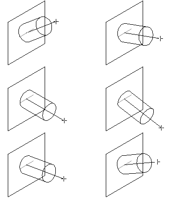
If a circle, polygon or similar shape is rotated up/down or left/right relative to the 3D plane, it is called an out-of-plane shape.
|
|
|
|
|
Select one of the two out-of-plane choices, in which case the shape is rotated about the 'horizontal' or 'vertical' axis of the 3D plane. The diameter of an out-of-plane circle may be measured in one axis, as indicated by the horizontal or vertical line above, or by a single line in the sample window in a tool's dialog box.

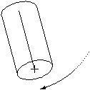
To draw an out-of-plane shape, you click at the center of the object and then move the mouse to draw a line that represents the centerline of a rod, as shown above, or the 'axle of the wheel' in the case of a circle.
When you do this, the angle of the line shown in the Edit Window is a correct 3D angle, thus a line normal to the view plane will be 0°. If you want to draw a rod or circle that is tilted up 33.5° relative to the view plane, just tab into the Edit Window and type the angle.
In the case of rods and spirals, the Edit Window will also show the length, and this is also a correct 3D length that you can edit in the Edit Window.
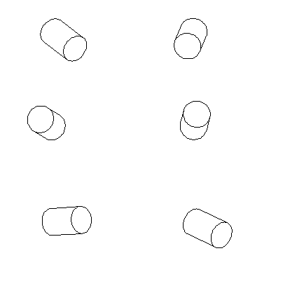
Free Rotation. Okay, great. You can draw shafts, nuts, spirals and helical springs of a given length and diameter on the current view plane or tilted up/down/left/right relative to the plane. But life isn't like that, and sometimes you want to draw these things at any angle in space. No problem.

Free Rotation
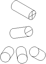
This is known as a 'free rotation', and it solves one of the most difficult problems in drafting and technical illustration.

For a free rotation, begin to draw the shape either in-plane or out-of-plane, and then press and hold the Shift key to rotate the object in three dimensions. Note that if you are drawing a rod with an interactive length, the length is 'frozen' at the time that you press the Shift key. If you don't like the length, then you may release the Shift key and try again. Once you begin a free rotation, you may not use the Edit Window.

Again, let's remember than an axonometric drawing is a distortion of reality. Since 'circles' are dimensionally accurate in two axes for in-plane circles, and in one axis for out-of-plane circles, the major axis length of an ellipse used to represent a circle is longer than the diameter of the circle.
By the same token, a free-rotation circle may not be measured in any convenient way, but it does have a definable size and shape for a given 'diameter'. The major axis length of the ellipse used is the same as for the in-plane and out-of-plane 'circles', and the minor axis length is computed as a location on a sphere. This leads to the insanity that if you want to draw a 6-inch diameter barrel of a cannon where you are looking directly down the bore of the cannon, the hole will be represented by a circle, but that circle must be larger than 6 inches. This sort of thing can be mind-boggling, but please-please-please don't call Engineered Software to chat about this 'interesting' phenomenon.