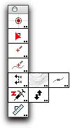
Topo Tools Palette |
|

Topo Tools Palette |
|
This tool palette consists of ten tools that help in the construction and analysis of topo drawings.
TopoTools and Topography ToolsThe first topographical tools for PowerCADD were developed by Paolo Rossi in Italy. His external, known as Topography Tools offers a series of tools for placing topo points, slope interpolation as well as the import and export of topo survey data. After seeing these tools, I began to develop some ideas on how topograpical tools might operate. Working with a number of civil engineers and architects, I have developed TopoTools and collaborated with Engineered Software and Paolo Rossi to establish a standard way to store a Z height and topo data in a PowerCADD drawing. I regret any overlap of capabilities, and I urge everyone to investigate Topography Tools and the additional capabities it offers, particularly the ability to import and export survey data. Alfred Scott |
A PowerCADD drawing consists of two-dimensional objects, however PowerCADD provides the capability to store additional information with each object. The Z height of an object is stored this way, and it is optional. Thus, most objects will not have a Z height at all.
To get started, use the Z Needle to assign a Z height to an object in the drawing. Once you do this, many of the tools in TopoTools will suddenly come alive when they ?see? the Z height of the object.
This is a new type of object which shows the X and/or Y location of the object in the drawing as dimension text. When the object is moved, the dimension text changes to the current X and Y location. The dimensions may be single or dual dimensions. The Dimension Point tool and Datum Dimension tool place dimension point objects in the drawing. These objects do not have a Z height, but you can use the Z Needle tool to give them a Z height.
Dimension point objects have a single marker, which can be literally any PowerCADD object, including groups of objects, pictures, etc. They are always a fixed size and are normally centered on the object, but not always?as in the ca
These are a special type of dimension point objects which always have a Z height. As placed by TopoTools, the markers will be a reference point, or a vertical or diagonal cross.
Topo point objects may show only the Z height as dimension text, and may also have additional text for the survey point number and a description. While you may edit the survey point number and description with the Text tool, this will not work well because the text will be replaced with the original internally-stored point number and description.
The topo point dimensions may be single or dual dimensions. The topo point object may have a leader, which can be a polygon or a smooth B-spline.
 Benchmark Tool
This tool lets you set the global drawing origin by specifying the location of a benchmark in the drawing.
Global CoordinatesThe X and Y coordinates in a PowerCADD drawing are all relative to the drawing origin, that is the zero-zero point in the drawing. You set this by dragging from the top left corner of the ruler. There are drawings where the drawing coordinates are relative to an off-page origin. Survey and topographic information is normally in the State Plane Coordinate system, but there is also the North Americal Datum, UTM and other similar systems. Additionally, aircraft and ship design drawings use their own datum points to specification locations in the vehicle. To accommodate this, PowerCADD provides an optional, alternative drawing origin called the Global Origin. It's just a second drawing origin that you can use, but because the zero-zero point is almost always off the page, you must specify this location by typing the coordinates. Do this in Drawing Setup : Show. However, calculating the location of the origin relative to your drawing can be difficult. |
The Drawing Benchmark tool simplifies the process. Like a surveyor, who drives a stake in the ground to establish a benchmark location, you use the tool to establish a benchmark location in your drawing, then specify the location of the benchmark in your global coordinate system and finally you set the global drawing origin.
? Select the Drawing Benchmark tool from the TopoTools tool palette.
The drawing benchmark is shown as a red dot, and a leader line extends to the cursor so you can easily find the benchmark.
? Click in the drawing to establish a new location for the benchmark.
--or--
? Click in the handle of the benchmark and move it to the desired location.
Once you have located the benchmark, press the Option key and select the Drawing Benchmark tool from the (TopoTools) tool palette. The following dialog will appear:
? Type the X and Y coordinates of the drawing benchmark expressed in the global coordinate system.
? Select Set Global Origin. The tool will calculate the location of the origin and set the global origin.
Now, when you draw, the X and Y coordinates of the drawing will be relative to the global origin.
You can place a benchmark indication in the drawing.
? Press and hold down the Shift and Option keys. The cursor will change to a DumpTruck cursor.
? Click in the drawing.
A benchmark image will be placed in the drawing. This is a group of PowerCADD objects. If you move the drawing benchmark, this indication in the drawing will no longer be applicable, and you will need to place another up-to-date image.
 Slope Offset
Tool
Slope Offset
ToolThis tool allows you to duplicate and move an object with a Z height to a new location and to change the Z height on the new object to a specified slope.
In the dialog, you set the slope and whether it is an up or down slope.
To use the tool, click on an object in the drawing with a Z height and drag the duplicate object to a new location. The new object will have a new Z height as calculated by the specified slope.
Specify a slope in the dialog, say 10% up or down, then click on any object with a Z value and drag to a new location in the drawing. The tool duplicates the object (just like the Super Arrow tool) and moves it to a new location and it changes the Z value of the new object to match the specified up or down slope.
 Slope Measure
Tool
Slope Measure
ToolThe Slope Measure tool lets you click on one object with a Z value and drag to another object with a Z value, then it reports the slope between the two objects.